
Date
Friday, 15 Sep 2017 7:30 PM
We are continuing to building a MIDI signal merger.
At the end of our last meeting, we established an initial block diagram as follows:
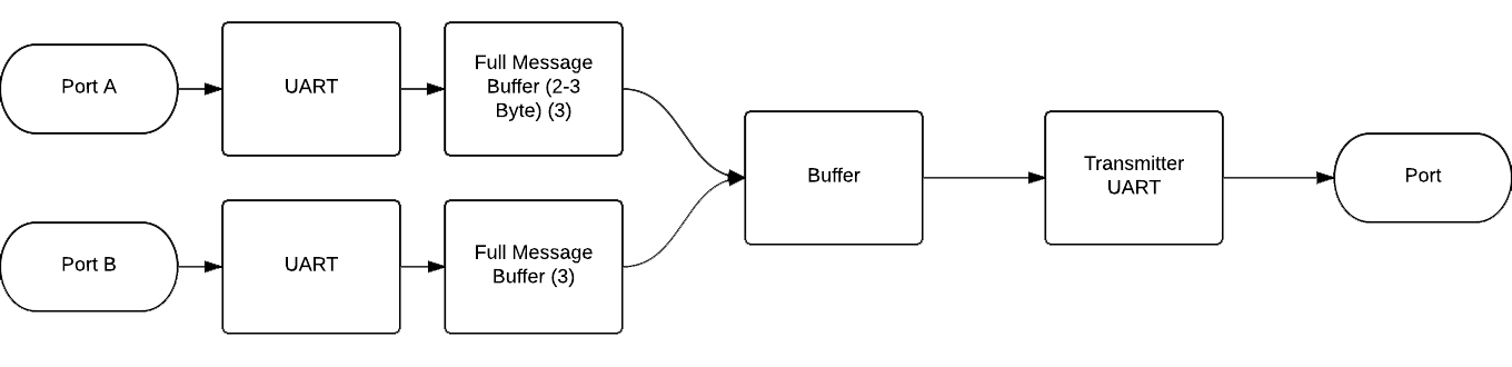
I’ve found that Lattice Includes an example on UART.
Some details of that can be found here:
https://www.mocomakers.com/fpga-midi-signal-merger/
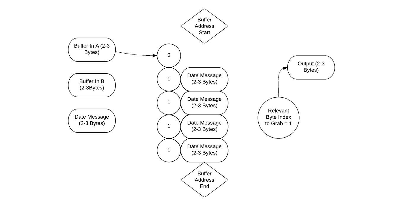
We need to flush out the primary buffer, and we have two options.
Option 1:
Option 2:
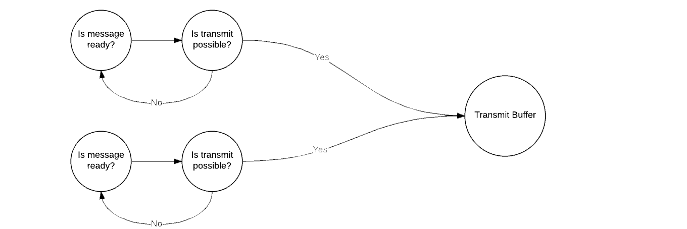
Option 1 is a robust option with scale-able ‘memory-space’ for signals. It uses a variable to track which location the relevant of the relevant message to push. The second option is a more simple series of “if” statements, that does not have a large memory buffer. A limited memory buffer, may be okay, for simple merging.
This project adds an example use case for the Fipsy FPGA our community is developing for Kickstarter. We are looking to document our process, so others can reproduce our project, and learn FGPAs.
“MIDI (Musical Instrument Digital Interface) is a protocol developed in the 1980’s which allows electronic instruments and other digital musical tools to communicate with each other. MIDI itself does not make sound, it is just a series of messages like “note on,” “note off,” “note/pitch,” “pitchbend,” and many more. These messages are interpreted by a MIDI instrument to produce sound. “
– Source:
http://www.instructables.com/id/What-is-MIDI/
At this meeting we will:
• Review the DIY Game Glove, which is now a completed project and was a big success at Escape Velocity!
• Revisit the code for the Turn Table project
• Begin planning for the FPGA MIDI Merger project. Our goal is to establish a block diagram of the FPGA ‘modules’ – or main functionalities – needed to implement the merger.
For those who are interested, the following background material, and side projects will be useful to us:
An introduction to MIDI:
https://learn.sparkfun.com/tutorials/midi-tutorial/all
• From this we take away that MIDI uses serial communication. We care about UART lines for TX and RX in particular.
http://michd.me/blog/yearproject-fpga-midi-synth/
• Notice the FPGA block diagram this project used. We can base our block diagram off of this one.
http://www.indiana.edu/~emusic/etext/MIDI/chapter3_MIDI4.shtml
• The table on this page shows the nuts and bolts of the Signal and Data bytes we are focusing on. We will not do a full MIDI specification, just the basics of playing notes, shown in the table.
http://www.instructables.com/id/Send-and-Receive-MIDI-with-Arduino/
• This is an Arduino MIDI interface, from which we can draw many inspirations
• We learn that we need to interface with 3 MIDI cable pins, one for data, one for a common ground, and one to send junk data back to the sender.
• Depending on how things turn out, we may want to implement MIDI on an Arduino for testing purposes. The project also shows who to couple MIDI inputs from Ardunio’s serial messaging (via the USB) to a Windows computer, in a useful way.